Linear Actuator Installation Guide

Installation Guide

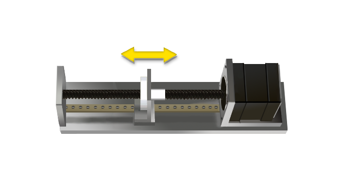
1.External Lead Screw Linear Actuator + Linear Guide

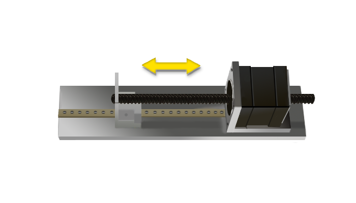
2.Non-Captive Lead Screw Linear Actuator + Linear Guide


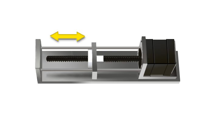
3.External Lead Screw Linear Actuator + Guided Rod


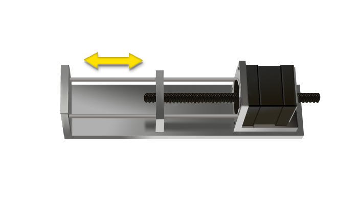
4.Non-Captive Lead Screw Linear Actuator + Guided Rod


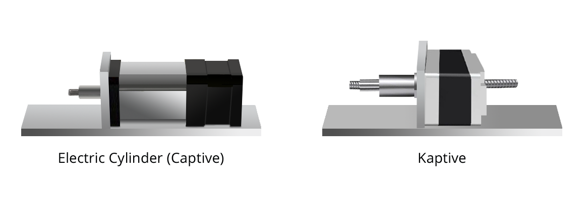
5.Electric Cylinder/Kaptive Lead Screw Linear Actuator Mounted to Load Directly

** Please select one of installation guide according to your application and it is strongly recommended from DINGS' to use our linear actuator in longer life cycle and for proper usage.

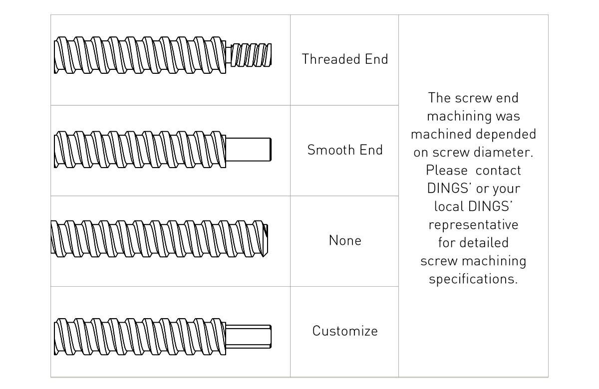
Screw End Machining

opt screw end machining

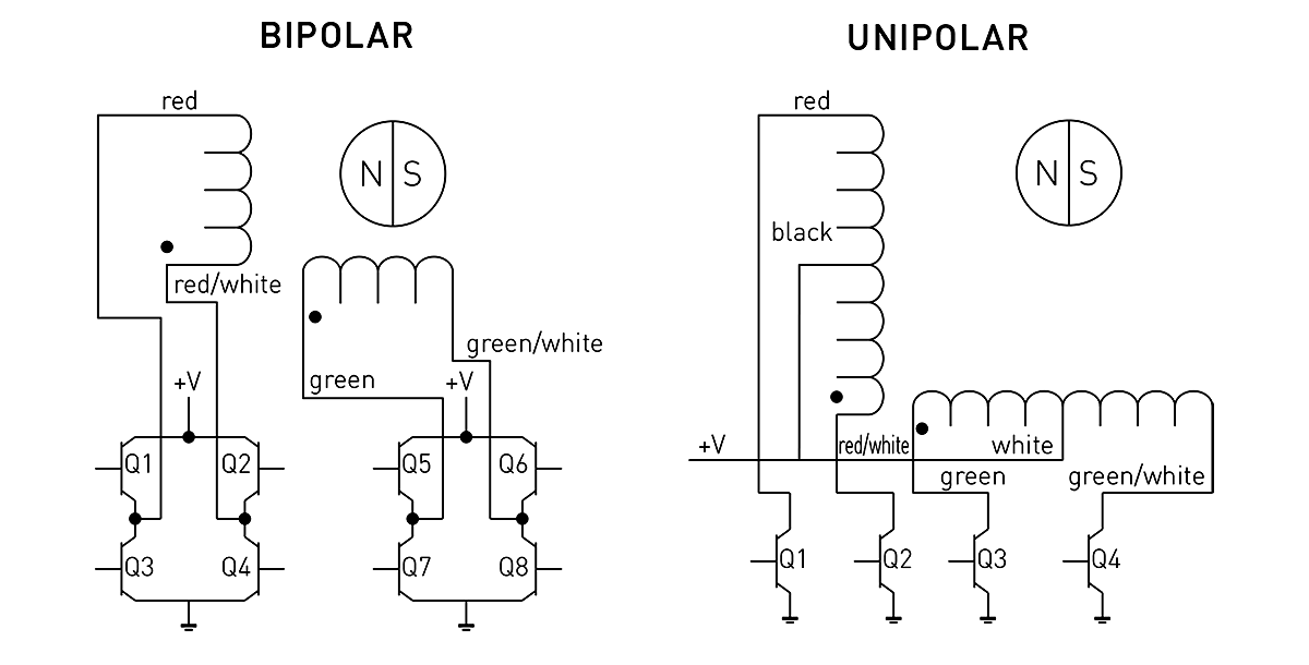
Stepping Sequence

stepping sequence images
Bipolar Q2-Q3 Q1-Q4 Q6-Q7 Q5-Q8
Unipolar Q1 Q2 Q3 Q4
Step
1 ON Off ON Off
2 Off ON ON Off
3 Off ON Off ON
4 ON Off Off ON
5 ON Off ON Off

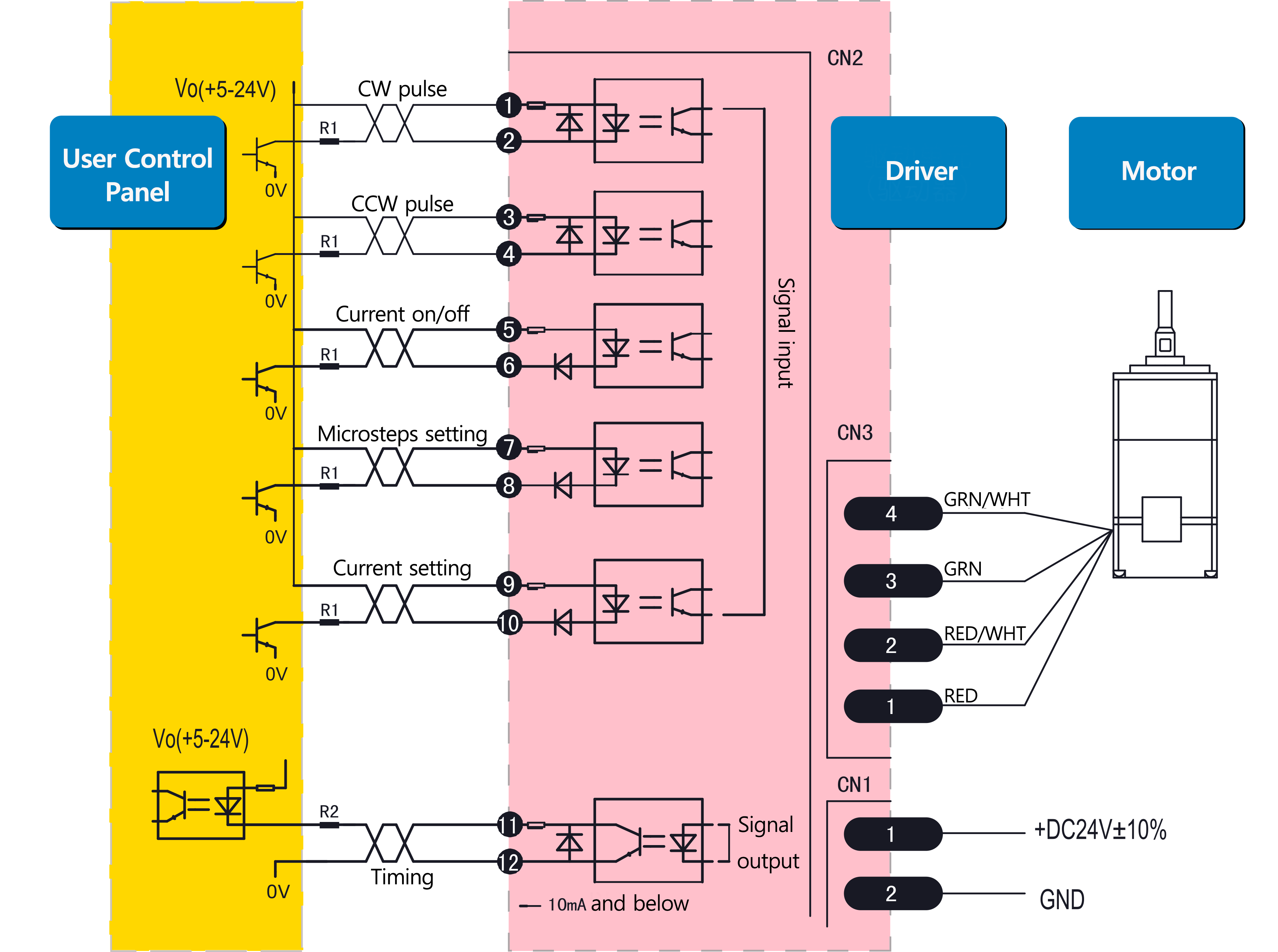
Typical Electrical Connection

typical electrical connection image

External Nut Strength

Item Motor Size Anti-backlash Nut Standard Nut Triangle/Trimming-cut Nut Mounting Hole Dimension Screw size
customer used
Installation Torque /Max. Installation Torque /Max. Installation Torque /Max.
1 14mm 0.8kgf.cm 1.0kgf.cm φ2.6/φ3.2 M2.5 or M3 and smaller
2 20mm 0.8kgf.cm 1.0kgf.cm φ2.6/φ3.2 M2.5 or M3 and smaller
3 28mm 0.8kgf.cm 4.0kgf.cm φ2.6/φ3.2 M2.5 or M3 and smaller
4 35mm/42mm 4.0kgf.cm 5.5kgf.cm 5.5kgf.cm φ3.2 M3 and smaller
5 57mm/60mm 6.0kgf.cm 6.0kgf.cm φ3.5/φ5.1 M3 or M5 and smaller
6 86mm 18kgf.cm φ7.0/φ8.0 M6 and smaller

Operation Guides

  • Do not dismantle the motor in any case.
  • Do not apply radial force to the screw. Do not lift, hang, push or pull the screw during usage or transport.
  • Do not add any lubrication to the nut and screw. Protect the grease from being wiped off and no other grease shall be used except those from DINGS'.
  • Measures should be taken to protect the leadscrew surface from dust.
  • Do not drop the motor or screw during usage.
  • Do not apply force or tension to the lead wire.
  • When using a chopper driver, please set the current (RMS) to the rated current of the motor. Overdriving is not recommended, as it could overheat the motor and cause the coils to melt/burn without initial testing.
  • Operate in ambient temperatures between -20°C to +50°C.
  • To get the designed lifetime, actual load should be lower than 50% of the calculated data and try to avoid the missing step or stuck. Don't drive the motor beyond its designed stroke for Captive and Kaptive structure. Impact, immediately stop or start should be avoided, too.
  • Storage conditions: Ambient temperature and pressure, relative humidity <75%, clean, noncorrosive environment.

Trouble Shooting

Common Failure Cause Analysis Processing Methods
No Running Poor Connection Re-connection
Driver Alarm Power Off and Re-boot after checking
Actuator stuck Remove load, ensure actuator operates smoothly without load
Motor winding or insulation damaged Contact DINGS' for maintenance
Abnormal operation after starting up Resonance Enhance microsteps to change travel speed
Lead Screw Bend Contact DINGS' for maintenance
Phase Loss Contact DINGS' for maintenance
Vibration, Noise Low-frequency Vibration Adjust driver microsteps to change travel speed to avoid resonance
Phase Loss Contact DINGS' for maintenance
Abnormal heating Over Current Regulate current value to achieve proper rating range
Over Supply-voltage Reduce supply-voltage
Extended period of holding The holding current should be halved or adjusted to smaller value
Step loss Overload on the Load Side Reduce load or re-selection
No frequency raising or lowering when programming When motor starts, it needs to be accelerated from low to high
Insufficient thrust Driver Failure Repair or replace driver
Load is too high Reduce load or resize actuator
Damaged Nut Contact DINGS' for maintenance
Lead Screw Bend or Runout at the End of Lead Screw Damage in Transportation or Improper installation or Improper Operation Contact DINGS' for maintenance
Other Failures Contact DINGS' for maintenance