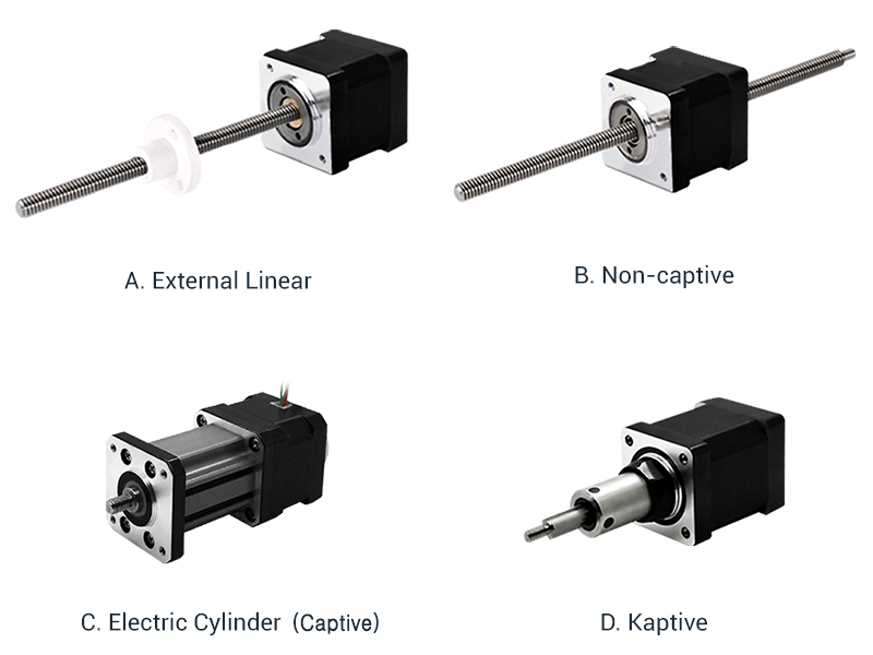
All references for lead screws in DINGS’ have following characteristics.
DINGS' Linear systems are manufactured from high quality materials. Because of variable effects of friction, lubrication and cleanliness, exact life cycle can not be predicted.
Here is a general overview of the Output Thrust vs. Motor Size:
| Motor Size(mm) | Max Thrust(N) | Recommended Load Limit(N) | |
|---|---|---|---|
| Lead Screw Linear Actuators | 14 | 19 | 15 |
| 20 | 70 | 45 | |
| 28 | 150 | 140 | |
| 35 | 300 | 230 | |
| 42 | 600 | 230 | |
| 57 | 1300 | 910 | |
| 60 | 1560 | 910 | |
| 86 | 2400 | 2270 |
After estimating the required thrust and choosing a motor size that may fit your application, the speed and acceleration of the load must be considered and evaluated to choose and appropriate screw lead.
Due to the nature of lead screws, the output speed and output thrust achievable by a motor/lead screw combination are two proportional. increasing the required thrust will lower the achievable speed for a motor/lead screw combination. Therefore, the maximum output force of a system is lowered for applications that requires higher speed.
For complete motor/lead screw selection data, please refer to the Speed vs. Thrust curves for each motor size.
Although these two steps provide a solid foundation in motor/lead screw selection, other variables must also be considered:
Because of the numerous variables involved in motor selection. We highly remommended for users to proceed with physical testing to accurately determine the motor/lead screw combination required for a given application.
One of the most common methods of moving a load from point A to point B is through linear translation of a motor by a mechanical lead screw and nut.
This section is here to assist and refresh your understanding of the basic principles of lead screw technology. Some basic design consideration are as follows:

Although this section aims to provide a rough guideline to select a motor/lead screw combination that best fits an application, we recommend to contact our application engineering staff or sales representatives for further assistance with the motor selection process.