The lead accuracy of a ball screw refers to the representative deviation and variation of the travel error relative to the effective nut travel or the effective threaded length of the screw shaft. It also includes the variation measured over any 300 mm length of the effective thread and over one revolution (2π rad).
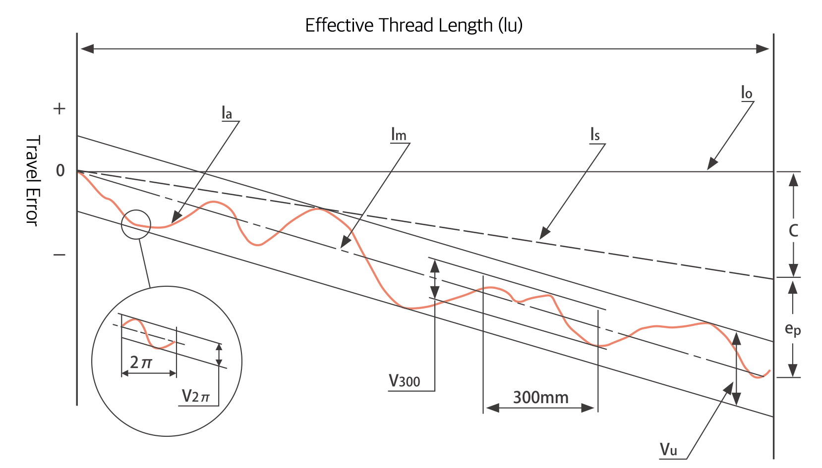
[Travel Error Diagram]
Nominal Travel Distance The axial travel distance of the nut corresponding to any number of revolutions based on the nominal lead
Target Reference Travel Value (T) A corrected lead value that accounts for the effects of temperature rise and load deformation, serving as the target reference for travel distance
Standard Travel Distance The travel distance produced by the nut when rotating any number of revolutions based on the target reference travel value
Actual Travel Distance The actual axial travel distance produced by the nut for a given rotation angle of the screw shaft
Representative Travel Distance A best-fit line reflecting the trend of actual travel distance, derived from actual travel data within the effective travel range or effective thread length of the ball screw using the least squares method or equivalent
Representative Travel Error (eₚ) The difference between the representative travel distance and the standard travel distance within the effective travel range of the nut or the effective thread length of the screw shaft
Variation (Vᵤ) The maximum variation of actual travel distance between two lines drawn parallel to the representative travel distance line
Variation (V₃₀₀) The maximum variation of actual travel distance over any selected 300 mm section within the effective thread length
Variation (V₂π) The maximum variation of actual travel distance over any selected one-revolution (2π rad) section within the effective thread length
| Effective Threaded Length (mm) |
Accuracy Grade | C3 | C5 | |||
|---|---|---|---|---|---|---|
| Over | Up to | ±ep | Vu | ±ep | Vu | |
| - | 100 | 8 | 8 | 18 | 18 | |
| 100 | 200 | 10 | 8 | 20 | 18 | |
| 200 | 315 | 12 | 8 | 23 | 18 | |
| 315 | 400 | 13 | 10 | 25 | 20 | |
| 400 | 500 | 15 | 10 | 27 | 20 | |
| 500 | 630 | 16 | 12 | 30 | 23 | |
| 630 | 800 | 18 | 13 | 35 | 25 | |
| 800 | 1000 | 21 | 13 | 40 | 27 | |
| Precision Grade | C3 | C5 | |||
|---|---|---|---|---|---|
| Item | V300 | V2π | V300 | V2π | |
| Permissible Value | 8 | 6 | 18 | 8 | |
| Precision Grade | C7 | C10 |
|---|---|---|
| V300 | 52 | 210 |
The representative travel error (ep) for C7 and C10 is calculated using the following formula:
ep = ± (lu / 300) × V300 lu : Effective thread length (mm)
The standard material, heat treatment, and hardness of DINGS' ball screws are shown in the table below. Values may vary slightly depending on the series and model; please refer to the specifications provided by DINGS'.
| Component | Material | Heat Treatment | Thread Surface Hardness |
|---|---|---|---|
| Screw Shaft | SUJ2 (JIS G 4105) | Induction hardening | HRC 58–62 |
| S55C (JIS G 4105) | Induction hardening | HRC ≥58 | |
| SUS440C | Quenched and tempered | HRC ≥55 | |
| Ball Nut | SCM420H (JIS G 4105) | Carburized and hardened | HRC 58–62 |
| SUS440C | Quenched and tempered | HRC ≥55 |
Note: S55C material is used for rolled ball screws, while SUJ2 material is used for ground ball screws.
In standard single-nut ball screws, a small axial clearance typically exists between the screw shaft and the nut.
Under axial loading, this inherent clearance combines with elastic deformation caused by the applied load, resulting in increased backlash.
To eliminate backlash, the axial clearance must be set to a negative value — that is, elastic deformation is intentionally induced between the screw shaft and nut in advance through preloading.
The combinations of axial clearance and accuracy grades for DINGS' ball screws are shown in the table below, along with the clearance symbols and allowable axial clearance values.
| Accuracy Grade | Axial Clearance | |||
|---|---|---|---|---|
| Z (Preload) | T (≤0.005 mm) | S (≤0.02 mm) | N (≤0.05 mm) | |
| C3 | ● | ● | ● | ● |
| C5 | ● | ● | ● | |
| C7 | ● | ● | ||
| C10 | ● | ● | ||
Preload is applied to eliminate axial clearance and minimize axial displacement under load, thereby increasing the rigidity of the ball screw.
The graph below shows the elastic displacement curves with and without preload.
As illustrated, applying preload reduces axial elastic displacement by approximately half compared to a clearance-type configuration, resulting in significantly improved stiffness.
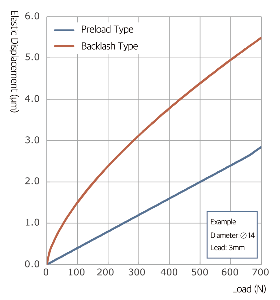
Elastic Displacement Curves of Ball Screw
The preload amount should be determined based on the required stiffness or allowable backlash. However, applying preload may result in the following effects:
Therefore, the preload amount should be set as low as possible while meeting performance requirements.
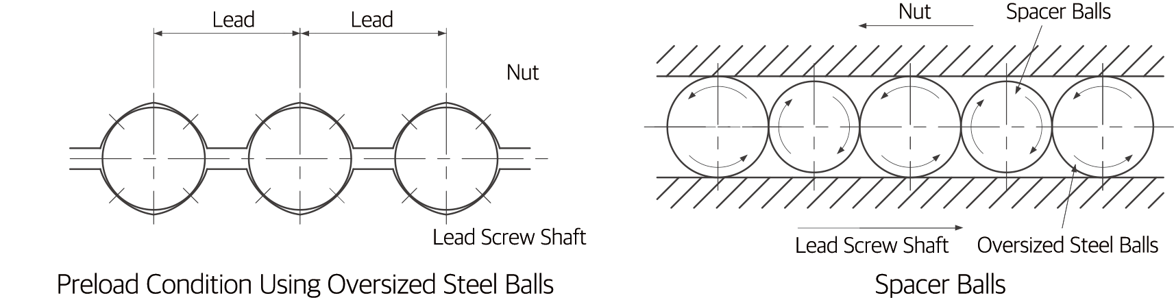
In ball screw preloading, the double-nut preload method is commonly used, where a shim (spacer) is inserted between two nuts to apply preload force.
DINGS' ball screws, however, take full advantage of the structural characteristics of miniature ball screws by adopting an "oversized ball preload" method, in which steel balls with a diameter slightly larger than the clearance between the screw shaft and nut are used to apply preload. This method eliminates axial clearance with a single nut, enabling a more compact design.
In addition, "spacer balls" — slightly smaller in diameter than the preload balls — are placed alternately between preload balls in the raceway, effectively preventing degradation of motion performance due to excessive preload.
Since the preload amount in a ball screw cannot be measured directly, it is common engineering practice to convert it into a preload running torque, which is then measured to indirectly monitor the preload condition.
The nominal value of preload running torque is specified in the specification drawing, with the actual value to be agreed upon between the supplier and the customer. To ensure effective management of the preload amount (i.e., zero axial clearance), preload running torque must be measured under strictly consistent conditions.
It should be noted that lubrication conditions and operating environments vary across different machines, and the actual measured running torque may deviate accordingly. Furthermore, the starting torque of a ball screw — the torque required to initiate motion — is generally slightly higher than the preload running torque, and this should also be taken into consideration.
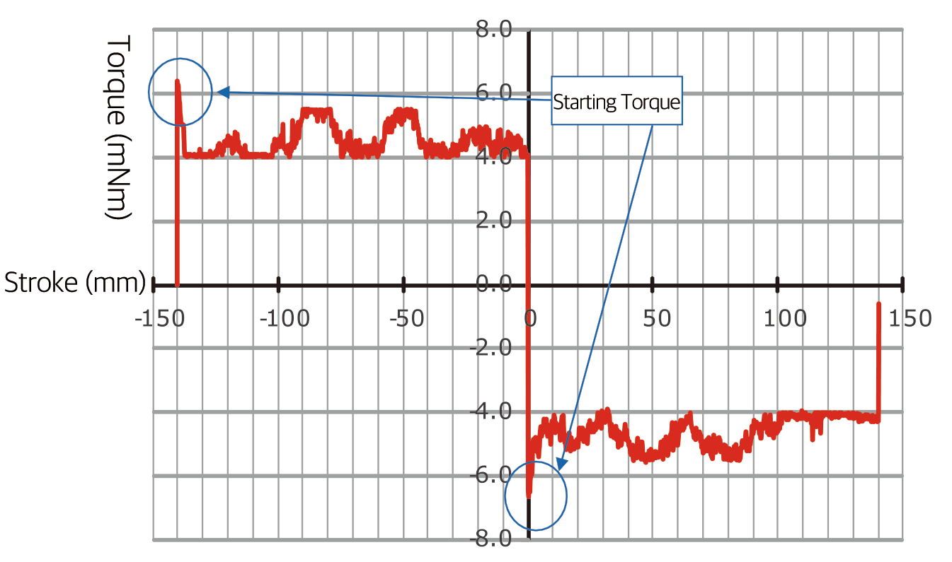
Preload Torque Variation Curve
Note: The torque variation illustrated in this figure has been intentionally exaggerated for explanatory purposes.
DINGS' ball screws are coated with rust-preventive oil for long-term storage. Before use, remove the oil with clean refined kerosene and apply lubricating oil or grease. Grease can be applied prior to shipment upon request; however, long-term storage with grease may cause rust.
Note: The rust-preventive oil is for corrosion protection only and provides no lubrication. Using the ball screw without removing this oil may reduce service life and cause increased torque or abnormal heat generation.
Lubrication is essential when using ball screws. Insufficient lubrication may cause increased torque and shortened service life. Proper lubrication suppresses temperature rise due to friction, loss of mechanical efficiency, and accuracy degradation caused by wear. Ball screws can be lubricated with grease or oil.
Selecting the appropriate lubricant according to the application is particularly important. For miniature ball screws, grease churning resistance may increase torque. DINGS' provides proprietary greases optimized for ball screw performance:
Recommended Lubricants
| Lubricant Type | Category | Product Name |
|---|---|---|
| Grease | Lithium-based grease | AFG Grease |
| Lubricating Oil | Slideway oil or turbine oil | Super Multi 68 |
When using grease lubrication, inspections should be conducted every 2–3 months; when using oil lubrication, inspections should be conducted weekly. During inspection, check the lubricant quantity and contamination, and replenish as necessary. When adding new grease, remove old and discolored grease as thoroughly as possible.
| Lubrication Method | Inspection Interval | Inspection Items | Replenishment / Replacement Interval |
|---|---|---|---|
| Automatic Intermittent Lubrication | Weekly | Oil quantity, contamination | Replenish appropriately at each inspection based on reservoir capacity |
| Grease | Initial operation: 2–3 months | Contamination, chips, foreign matter | Typically replenished once per year; adjust based on inspection results and remove discolored old grease |
| Oil Bath | Before daily operation | Oil level | Adjust appropriately according to consumption |